Motor vehicles have gone through much progress since their inception. Modern cars include autonomous and semi-autonomous driving, anti-lock braking systems, electric power steering, forward and rear collision warning, lane assistant, autonomous parking assistant, and automatic emergency braking. Advanced features such as GPS navigation, interior mood lighting, surround-view camera, advanced infotainment system, active antenna are standard in most modern vehicles.
Each vehicle feature is usually monitored and controlled by an individual Electronic Control Unit (ECU). In a modern vehicle, there are about 50 - 100 ECUs, with each ECU responsible for one or more functions. The ECU works with multiple sensors such as the engine temperature sensor, air pressure sensor, door sensor, etc. It receives information from the sensors and adjusts the vehicle parameters under control accordingly. Sometimes one ECU may need to communicate with other ECUs to perform a designated function. For example, if you forget your car key in the ignition, the corresponding engine control ECU communicates with the door ECU to keep the door open and the speaker ECU to sound the alarm.
ECU Communication via CAN Bus
There are several in-vehicle network (IVN) protocols for data transmission between ECUs inside a vehicle. The most popular communication mechanism in modern vehicles is the Controller Area Network (CAN) bus. It is a bi-directional serial communication bus that allows ECUs to communicate without using any complex wiring. A twisted pair cable with a characteristic impedance of 120Ω is used to transmit the data. One of the wires is called the CAN_Low (CAN_L) and the other, CAN_High (CAN_H), with a data transfer rate of 1Mbit/s. The ECU is connected to the CAN bus via a CAN controller, similar to a microcontroller that handles all the necessary data processing activities. There is a CAN transceiver that interfaces between the CAN controller and the CAN bus. It converts the transistor-transistor logic (TTL) signal into the actual differential voltage signal for the CAN bus to read and interpret. The CAN bus architecture is shown in Figure 1.
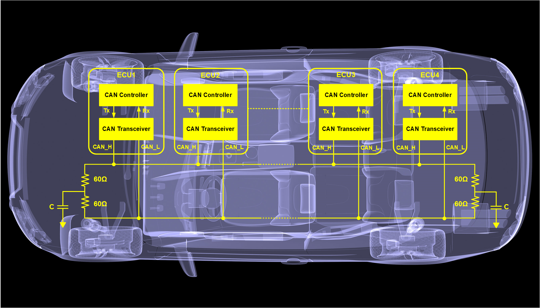 Figure 1. Automotive CAN Bus Architecture
Transient Protection of the CAN Bus
When designing a CAN interface system in a harsh automotive environment with 50 to 100 ECUs, ensuring sufficient protection from Electrical Overstress Events (EOS) is imperative. One of the primary causes of EOS is electrostatic discharge (ESD). Moreover, with the miniaturization of the electronic components, it is even more essential to protect the components from ESD threats and meet modern-day vehicles' safety and reliability requirements.
Transient protection can be achieved by placing a Transient Voltage Suppression (TVS) diode on a CAN bus data line to protect against transient events during the fast rise time in less than a nanosecond. Under normal operating conditions, the TVS diode presents a high impedance path to the protected circuit, so the device appears as an open circuit. It does not interfere with the rest of the circuit. During a transient event, the voltage on the terminals of the protected CAN transceiver can exceed safe operational limits. The TVS diode offers protection by providing a low impedance path so that the transient current is diverted away from the transceiver circuit. At the supposition of the ESD event, the TVS diode reverts to a high impedance state.
As mentioned before, the CAN Bus consists of two wires named CAN_H and CAN_L. CAN_H reaches 3.75V when transmitting any data. At the same time, the CAN_L drops down to 1.25V. When the CAN bus is not transmitting any data, both CAN_H and CAN_L remain at 2.5V. But we have to remember that a car generally uses a 12V battery. While jump-starts are typically performed with a 12V battery, certain service vehicles use a 24V battery for this purpose. So the first criteria to select a TVS diode is the reverse working maximum voltage or VRWM, which should be sufficient to protect the CAN transceivers if the car's 12V battery requires a jump-start from a 24V battery in an emergency. Another parameter that needs to be considered for selecting a TVS diode is the minimum breakdown voltage or VBR. It is the voltage when a TVS diode starts to conduct the current mentioned as a leakage current in the product's datasheet in any transient scenario. Semtech's µClamp2424PWQ (shown in Figure 2) is a four-channel device that can protect two sets of CAN_H and CAN_L in the CAN Bus architecture. µClamp2424PWQ has an operating voltage of 24V with a minimum breakdown voltage of 26.5V. These voltages are sufficient to protect the CAN transceivers even if the vehicle needs to be jump-started.
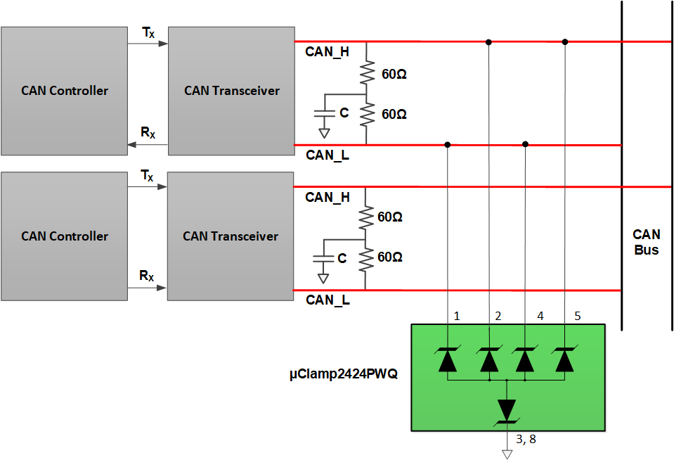
Figure 2. Possible ESD protection options of a CAN bus system
Now let us talk about another vital parameter called clamping voltage or VCLAMP. The VCLAMP is the voltage of a TVS diode that appears across the device at the maximum peak pulse current rating. VCLAMP determines the voltage that the device endures during a transient event. A lower clamping voltage is suitable for the protection of a CAN bus system or any other system. The typical clamping voltage of µClamp2424PWQ is 44V at a maximum peak current of 5A. Each device line is rated for a maximum EOS current of 5A (tp = 8/20μs).
The CAN_H and CAN_L lines carry a differential signal with a maximum data rate of 1Mbps. Since they are high-speed differential data lines, TVS diodes should protect the circuit during transient events while ensuring signal integrity by maintaining a very low line-to-line capacitance. µClamp2424PWQ offers an extremely low capacitance of 15pF (typ) and 18pF (max) between the line and the ground. This fact makes it a suitable candidate to protect the CAN transceivers without undermining the signal integrity.
Conformance to level 4 IEC61000-4-2 standard and AEC-Q qualification are also mandatory requirements for automotive system design. µClamp2424PWQ provides transient protection to ESD events at ±30kV (Air) and ±30kV (Contact) as per the IEC 61000-4-2 standard. The device is available in a DFN (2.5x1.0x0.55mm) package with state-of-the-art side wettable flanks for automatic visual inspection (AVI) post assembly. Figure 3 shows the features of µClamp2424PWQ.
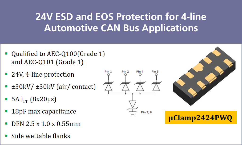 Figure 3. Features of µClamp2424PWQ
Conclusion
Semtech is a leading manufacturer of TVS diodes that protects many of the world's high-speed automotive communication buses. In the harsh automotive environment, careful design and proper TVS diodes are crucial for safeguarding the communication buses and interfaces. Semtech's well-performing and reliable portfolio of TVS products protects high-speed automotive CAN buses as well as other communication buses. Learn more about Semtech's product offerings for the automotive industry on our website.

Semtech®, the Semtech logo and uClamp® are registered trademarks or service marks of Semtech Corporation or its affiliates. Other product or service names mentioned herein may be the trademarks of their respective owners.