Over the past nine years since I have been with Semtech, Transmission Line Pulse (TLP) basics have always been one of the most important training topics for our new hires and customers. We have received many questions on why we emphasize and extensively rely on TLP analysis to provide the best solution to our customers. TLP testing doesn’t deliver the exact same waveforms as specified by industry standards like IEC 61000-4-2 or ESDA/JEDEC JS-001. It doesn’t guarantee that the IC or the system will pass testing for immunity to required electrostatic discharge (ESD) test levels. It is always recommended to verify all the results with the ESD generator after the TLP test is completed. So, why don’t we just simply test everything with our ESD generator, which is more familiar to most engineers and universally accepted? To answer that, I think it’s important to understand that TLP is not a replacement or an upgrade to the IEC tests, but it is complimentary to the ESD gun tests as an analysis tool. ESD gun test tells us YES or NO, but TLP can help us to understand WHY and HOW.
In recent years, TLP has become widely accepted and has been adopted by most of our customers globally. Its results have become one of the most important parameters for evaluating both component and system level ESD. Here are some tips on how TLP can be utilized as an analysis tool.
Transient Breakdown and Turn on Characteristics
The first step in selecting the ideal transient voltage suppressor (TVS) protection device is the identification of working voltage (VRWM ) and breakdown voltage (VBR ). The VRWM guarantees that TVS will stay at the OFF stage at or below the working voltage. TVS breakdown, snapback and holding voltage/current, can show when exactly the TVS switches between ON and OFF state. These are often tested with DC source with current in mA range and can be found on most datasheets for diodes. However, TVS diodes are designed to protect against transient threats, which have a pulse duration in ns to µs range. The TLP test specifies a 100ns pulse width. This pulse width more closely approximates real world ESD transients from a timing standpoint. Depending on the TVS technology, both rise time and pulse duration can have a large impact on these turn on characteristics.
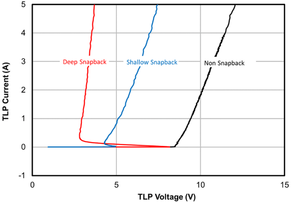
Figure 1: TLP comparison between different technologies
Semtech offers different TVS technologies to meet the needs for different applications. TLP comparison in Figure 1 shows the behavior of different types of TVS in the breakdown region. In general, snapback devices with lower breakdown voltage or holding voltage usually offer better clamping voltage, but these devices can potentially cause latch-up when a biased voltage is present at the protected line.
Dynamic Resistance (RDYN)
In an ideal world, a TVS will turn on at the breakdown voltage and then provide a SHORT path to conduct all transient energy away to GND. But in reality, the TVS will exhibit certain dynamic resistance after it starts to conduct. This resistance is usually in the mΩ range. Dynamic resistance (Figure 2), which is the slope of the IV curve, can tell how much your clamping voltage will vary when the current is increased. This is usually defined between 4A to 16A of device under testing (DUT) current, which is approximately the range of 2kV to 8kV in IEC pulse at 30ns.
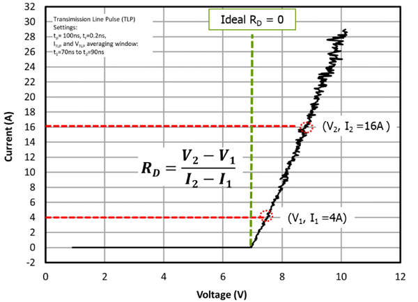
Figure 2: Dynamic resistance
Most ESD protection datasheets only include the clamping voltage waveform taken at 8kV with ESD generator, or some engineers only use the 8kV clamping waveform to select a device. Figure 3 is an example to show how we can compare two devices with different RDYN. TVS B with the higher dynamic resistance will exhibit high clamping after the cross point of the two curves, but still can provide a better clamping at lower levels. Since this crossing point can be at any level when comparing devices, the 8kV clamping graph may be only relevant at 8kV, but it’s not sufficient information for other levels. For example, in today’s high-speed applications where some data lines still struggle to pass even 2kV at system level, the dynamic resistance then becomes very critical. In other words, lower 8kV clamping voltage doesn’t always guarantee lower clamping voltages at all levels. On the other hand, the TVS with lower dynamic resistance can provide better clamping voltage even when its breakdown voltage is higher. One simple TLP IV curve with dynamic resistance can help to estimate if the clamping is low enough for the target levels.
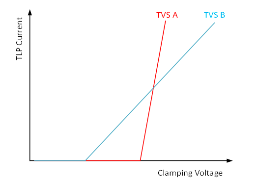
Figure 3: TLP comparison for devices
System-Level Analysis –Who Is Protecting Whom?
Most ICs have some kind of internal ESD protection structures. These provide very minimal protection, if at all. However, during a transient event, the protection internal to the IC can be triggered and will compete with the external TVS for ESD current. The path which has lower clamping and faster response will conduct more current. Figure 4 shows an example on how this can be visualized with the TLP analysis.
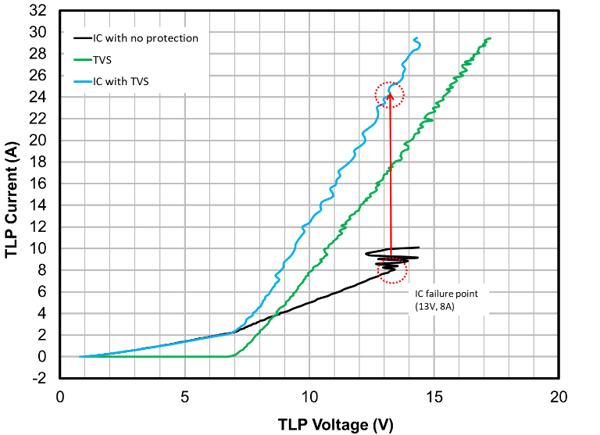
Figure 4: Evaluation on effectiveness of TVS
A TLP test is usually done in three steps: first is to evaluate the IC without any protection (black curve) to find its threshold. In this case, the IC failed around 13V and 8A. The second step is to evaluate the TVS (green curve), which will show how well TVS can protect the IC before you put it on the PCB. In this case, it takes about 16A for this TVS to reach to 13V which is the failure threshold of the IC; this indicates that the TVS will exhibit lower clamping than IC’s internal protection until at least 16A. The final step is to evaluate the combination of the IC and the TVS (blue curve). As shown in Figure 4, the IV curve follows the IC before the TVS’s breakdown voltage. And after the TVS turns on, both the IC and the TVS will be conducting current, but the overall IV curve will mainly follow the TVS, since the TVS provides the path with much lower impedance. The combination of internal protection and TVS can bring this failure threshold to at least 24A. If the TLP result shows that the internal protection circuitry clamps to a lower voltage than the TVS, or begins conducting even before the TVS can turn on, then the IC is “protecting” the TVS instead.
Consistency and Repeatability
Other advantages of the TLP analysis which make it to be an important analysis tool are the consistency of the waveform and high repeatability of the test results. It’s not uncommon to see dramatically different test results between test labs or test setups, especially during air discharge tests due to wider tolerances of ESD waveforms specified in standards and the complexities of ESD coupling path. Slight differences in test setup or test procedures can cause major differences in test results. With a well-defined 50Ω system, TLP testing delivers consistent and controlled waveforms to the DUT, which is very crucial for debugging and analysis. This also makes detecting any waveform distortion and the calibration process much faster and easier than IEC standard calibration.
Conclusion
Transmission line pulse testing is an important analysis tool when designing and evaluating system ESD protection. While it doesn’t perfectly correlate to industry ESD standards, it provides a very close first approximation by allowing comparison of internal IC protection structures to external TVS devices. This type of analysis can save time and money in the long run for designing system level ESD robustness. Semtech’s team of application engineers can aid in TLP analysis and System Efficient ESD Design (SEED) and help customers choose a protection scheme that works seamlessly in their system.

Semtech and the Semtech logo are registered trademarks or service marks of Semtech Corporation or its affiliates.