Today's automobile stands at the forefront of technological advancement with a vast array of sophisticated functions such as self-driving capability, GPS navigation, hands-free phone operation via Bluetooth further enhanced by Apple CarPlayTM and Android AutoTM along with many cutting-edge features that improve safety and comfort. The more features are added to an automobile, the more semiconductor components are used. The semiconductor components employed in automotive applications must satisfy the qualification criteria outlined in AEC-Q standards. This international standard specifies the qualifications necessary for packaged integrated circuits and discrete devices utilized in in-vehicle electronic systems. As more interfaces are used for high-speed signal transmission, more semiconductor components are added to automotive systems.
LVDS, GMSL, Ethernet and USB are high-speed interfaces commonly found in modern vehicles. A key consideration for ensuring reliable operation of high-speed interfaces in harsh automotive environments, is the provision of robust protection against electrical overstress (EOS) events. One of the primary culprits behind EOS damage is electrostatic discharge (ESD). It becomes increasingly imperative to shield electronic components from ESD threats while meeting modern-day vehicles' stringent safety and reliability standards. Now, the question is, what ESD standards should an automotive electronics manufacturer follow to ensure compliance with safety and reliability requirements? This blog post will delve into two prominent ESD standards: the IEC 61000-4-2, utilized for system-level ESD testing, and ISO 10605, used for ESD testing related to human contact inside or outside a motor vehicle. Lastly, this blog will also suggest how to safeguard automotive electronics with ESD protection devices.
IEC 61000-4-2
The IEC 61000-4-2 is a globally recognized ESD standard published by the International Electrotechnical Commission (IEC) for any electronic application at the system level in an end-user environment. This standard employs a test configuration replicating a scenario in which a charged human body comes into contact with an integrated circuit (IC), subsequently discharging potentially harmful ESD through the IC to the ground. The IEC 61000-4-2 test procedure entails discharging a capacitor through a resistor, effectively mimicking the scenario of ESD originating from a human body and impacting an integrated circuit (IC). You can refer to Figure 1 for the test setup. The test configuration involves a 150pF capacitor, which is charged to the specified voltage and discharged into a component pin through a 330Ω resistor.
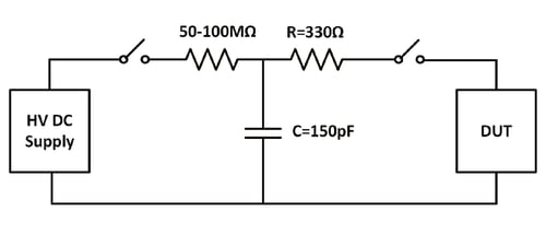
Figure 1. Simulation circuit of system-level IEC 61000-4-2
Figure 2 illustrates the contact discharge waveform per IEC 61000-4-2. This waveform has a very fast rise time, typically between 0.7 and 1 nanosecond. After the initial peak, there is a smaller second peak, and then the waveform decays. The IEC 61000-4-2 standard encompasses four levels, level 1 through level 4. These levels are contingent upon two primary testing procedures: the contact discharge method and the air discharge method. Refer to this blog for details of the IEC 61000-4-2 standard. According to this standard, ICs must endure at least level 4 ESD threats, which are ±8 kV contact discharge and ±15 kV air discharge.
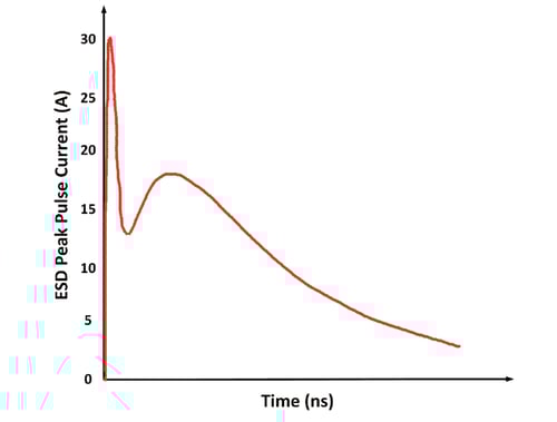
Figure 2. Contact discharge waveform at 8 kV waveform as per IEC 61000-4-2
ISO 10605
ISO 10605 is the global standard published by the International Organization for Standardization (ISO) that outlines the testing procedures for assessing the ESD endurance of electronic components employed in the automotive sector. ISO 10605 draws upon IEC 61000-4-2 as a foundation for addressing system-level ESD immunity. It encompasses elements such as positive and negative polarity testing, contact and air discharge methods, and resistance-capacitance network specifications. Nevertheless, this standard introduces multiple deviations from IEC 61000-4-2 tailored to only automotive applications.
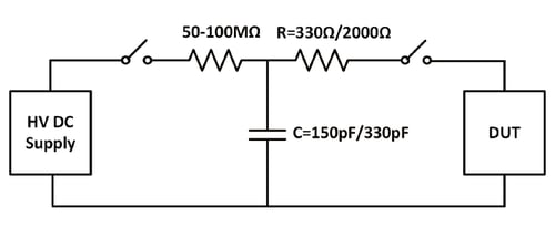
Figure 3. Simulation circuit of system-level ISO 10605
The testing process in ISO 10605, as shown in Figure 3, involves the discharge of a capacitor through a resistor, mirroring the procedure utilized in IEC 61000-4-2. In the ISO 10605 standard testing, two resistors, measuring 330Ω and 2000Ω, are employed to replicate varying types of ESD scenarios. The 330Ω resistor simulates a human body discharge through a metallic object, while the 2000Ω resistor emulates a scenario where a human body discharges directly through the skin. Additionally, the testing is conducted at two different capacitance values: 150pF and 330pF. A charging capacitance of 330pF is used in the ISO 10605 testing simulator when dealing with a human touch on vehicle areas accessible exclusively from inside the vehicle. For human touch in the areas that are only accessible from the outside of the vehicle, a capacitance of 150pF is used. In both cases, one can choose a resistance of 330Ω or 2000Ω, depending on the ESD scenarios they want to create. Typically, test voltages fall within the range of ±2kV to ±15kV for contact discharge and ±2kV to ±25kV for air gap discharge. In cases where areas are accessible both from the outside and inside of the vehicle, it is worthwhile to conduct tests using both generator capacitance values alongside maximum test voltages of ±15kV and ±25kV, respectively. However, it's important to note that certain automotive manufacturers may establish their unique specifications, and specific components might necessitate testing at much higher thresholds. Notably, the test configuration utilizing a 330pF capacitance and a 330Ω resistor represents the highest energy and current among all ISO 10605 test parameters. Table 1 summarizes the use of component values for the IEC 61000-4-2 and ISO 10605 standards, and Figure 4 shows the contact discharge waveforms at 8kV per ISO 10605 when discharge resistors are 330Ω and 2000Ω.
| Component | Value | Representation | IEC 61000-4-2 | ISO 10650 | Position |
| Resistor |
330Ω |
Human body discharges through a metallic object | ✓ | ✓ | |
|
2000Ω |
Human body discharges through the skin | ✓ | |||
| Capacitor | 150pF | Capacitance between human body and ground | ✓ | ✓ | Human body contact outside of the vehicle |
| 330pF | Capacitance between human body and vehicle seat | ✓ | Human body contact inside of the vehicle |
Table 1. RC network parameters used in IEC 61000-4-2 and ISO 10605 simulator
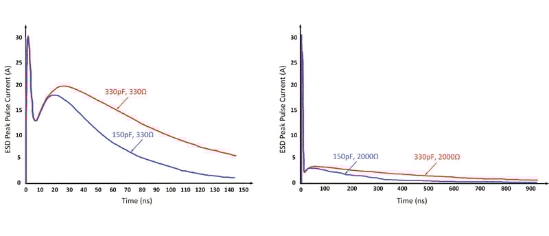 Figure 4. Contact discharge waveform at 8kV as per ISO 10605: Discharge Resistance 330Ω (Left), 2000Ω (Right)
Differences Between IEC 61000-4-2 and ISO 10605
Now that we understand both standards let us summarize the basic differences between these two:
- Although both IEC 61000-4-2 and ISO 10605 pertain to ESD testing, they serve distinct purposes and target different electronic systems. IEC 61000-4-2 has a broader scope, making it suitable for various electronic products, including consumer electronics, industrial equipment, and more. In contrast, ISO 10605 is customized for the automotive sector, addressing ESD testing requirements unique to that industry. Manufacturers should select the relevant standard based on their product category and intended use.
- The IEC 61000-4-2 simulator uses 330Ω and 150pF for the RC network, whereas ISO 10605 uses two resistors of 330Ω and 2000Ω and two capacitors of 150pF and 330pF that provide four possible RC network combinations.
- 150pF/330Ω
- 150pF/2000Ω
- 330pF/330Ω
- 330pF/2000Ω
- The suggested test voltage of IEC 61000-4-2 is ±15kV for air discharge. ISO 10605 also offers a test voltage of ±15kV for air discharge when the components under test are accessible from inside the vehicle. However, if the parts under test are accessible from outside the vehicle, a severity level of ±25kV for air discharge is suggested. However, as mentioned before, some automotive manufacturers may require testing at much higher limits, as much as ±30kV.
- The IEC 61000-4-2 test necessitates a repetition rate of twenty discharges per second, while the ISO 10605 standard mandates ten discharges per second.
- The last distinction lies in how the device under test (DUT) is grounded in both standards. In IEC 61000-4-2, the typical grounding method involves using a metal ground plane or a horizontal coupling plane (HCP) to establish an electrical connection with the ground reference plane (GRP) via a resistor strap. In contrast, ISO 10605 specifies the use of a conductive ground plane, which is basically a horizontal coupling plane (HCP), often constructed from metal or other conductive materials, to represent the vehicle's chassis. The DUT is positioned on this horizontal coupling plane to simulate the electrical grounding system found in a vehicle.
ESD Protection With Circuit Protection Devices
Shielding against ESD can be achieved by placing a transient voltage suppression (TVS) diode on either a data or a power line. TVS diodes are solid-state diodes engineered to respond swiftly to voltage surges, clamping the voltage to a predetermined level before it enters the circuit, all within a fraction of a nanosecond. In typical operational scenarios, the TVS diode presents a high-impedance pathway to the safeguarded circuit, effectively behaving like an open circuit. However, when a transient event occurs, the TVS diode swiftly shifts to a low-impedance state, redirecting the transient current away from the circuit and providing essential protection. Once the ESD event subsides, the TVS diode returns to its high-impedance state, ready for subsequent safeguarding.
Safeguarding Automotive Electronics With TVS Diodes From Semtech
To design automotive systems effectively, it's imperative to adhere to both the level 4 IEC 61000-4-2 and ISO 10605 standards, along with obtaining AEC-Q qualification. Moreover, in most automotive applications, including packages featuring side-wettable flanks has become an essential requirement. Semtech offers a versatile portfolio of highly efficient and trusted TVS diodes designed to address various automotive needs and applications. Seamless integration is facilitated through a comprehensive selection of packages featuring wettable flanks, simplifying automatic optical inspection. Semtech's automotive TVS diodes meet the demanding IEC 61000-4-2 and ISO 10605 ESD standards and offer low clamping voltages, significantly enhancing immunity.
Let's explore two of Semtech's advanced TVS diodes, which provide robust protection for high-speed data buses and other communication interfaces within vehicles.
2-Wire Ethernet
With the growing demand for increased bandwidth in automobiles driven by an expanding array of features, Ethernet technology is being utilized to meet these requirements. When developing a system that implements a high-speed interface such as Ethernet in a challenging automotive environment, it becomes crucial to guarantee the presence of adequate ESD protection. This is essential to ensure dependable operation even in the face of undesirable transient events.
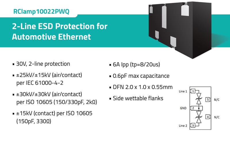
Figure 5. Features of RClamp10022PWQ
Semtech’s RClamp®10022PWQ (Figure 5) is a 2-line interface solution designed for ESD protection of automotive Ethernet interfaces. This part provides an operating voltage of 30V and a typical clamping voltage of 28V at 6A peak pulse current. RClamp10022PWQ provides transient protection at ±25kV (air) and ±15kV (contact) as per the IEC 61000-4-2 standard and ±30kV (air) and ±30kV (contact) as per the ISO 10605 standard (Test conditions: 150pF/330pF, 2kΩ). It has a maximum junction capacitance of 0.6pF between I/O pins and GND. RClamp10022PWQ is available in a 5-pin DFN package (2.0 x 1.0 x 0.55 mm). Rclamp10022PWQ is designed for OPEN Alliance Ethernet interfaces in automotive applications and is qualified to AEC-Q100, Grade 1 and AEC-Q101.
LVDS
Low Voltage Differential Signaling (LVDS) technology is frequently employed for the high-speed transmission of images within a vehicle. LVDS serves as a high-speed, long-distance digital interface used for data communication over twisted pair cables. The data or image transmission rate achievable with an LVDS interface typically ranges from 650Mbps to 1.3Gbps. Since the interface aims to maintain high-speed content transmission, it becomes crucial to incorporate an ESD protection device characterized by low line-to-line capacitance. This is essential to preserve signal integrity while transmitting data or images.
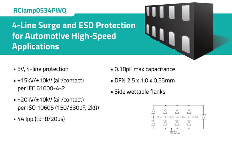
Figure 6. Features of RClamp0534PWQ
Semtech's RClamp®0534PWQ (Figure 6) is specifically designed to protect the high-speed differential lines of LVDS interfaces. It protects four high-speed data lines with a maximum junction capacitance of 0.18pF. It has an operating voltage of 5V and is rated for a maximum EOS Peak Pulse Current of 4A (tp=8/20µs). The typical clamping voltage at a peak current of 4A is 4.3V. RClamp0534PWQ provides transient protection as per the specification in IEC 61000-4-2 (ESD) at ±15kV (Air), ±10kV (Contact), and ±20kV (Air), ±10kV (Contact) as per the ISO 10605 standard (Test conditions: 150pF/330pF, 2kΩ). It is also compatible with IEC 61000-4-4 (40A EFT, 5/50ns) and IEC 61000-4-5 (Lightning 4A, 8/20µs). RClamp0534PWQ is available in a 10-pin DFN package (2.5 x 1.0 x 0.55mm) with wettable flanks. The flow-through package design of the device simplifies the PCB layout and helps maintain signal integrity.
Conclusion
These are only a few examples of Semtech's state-of-the-art automotive TVS diodes used to protect in-vehicle networks and interfaces. However, it's crucial to note that when the circuit specifications or data transfer speed change, the criteria for selecting the appropriate TVS diode also change. To ensure the defense of electronic components in your new design, consider exploring Semtech's Automotive protection portfolio. Semtech is one of the foremost manufacturers of TVS diodes, safeguarding numerous cutting-edge automotive electronic devices worldwide. In the demanding automotive environment, meticulous design and carefully selecting TVS diodes should always be considered when protecting communication buses and interfaces.
To learn more about Semtech's product offerings for the automotive industry, please download Semtech’s Automotive Selector Guide.

Browse Semtech's automotive circuit protection products online here.
Semtech®, the Semtech logo and RClamp® are registered trademarks or service marks of Semtech Corporation or its affiliates. Other product or service names mentioned herein may be the trademarks of their respective owners.