One single connecting port's name that is ingrained in our life is Universal Serial Bus or USB in short. It doesn't matter if I am a tech-savvy person or a Luddite, I have to use USB in every aspect of my life. Forget about me; my mom, who doesn't even know it is called USB, uses this port several times a day to charge her mobile devices. USB became very popular due to its ease of use and fast data transfer rate. Within a little over two decades, almost all consumer electronics gadgets come with one or more USB interfaces, from laptops and cameras to smartphones and wearables. However, things have changed a lot since the introduction. USB specification has evolved over 25 years from USB 1.0 in 1996 to the most recent version, USB4®. Figure 1 below shows the evolution of USB standards with the corresponding data transmission rates.
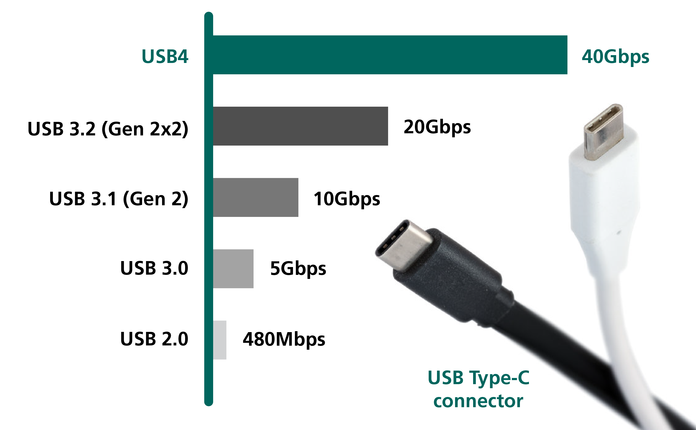 Figure 1. Evolution of USB standards
The USB communication protocol has evolved to support the rising demand for very high-speed communication and increasing levels of power delivery; the USB connector types have also evolved to meet the demands of the host devices and their innovative features. Like the previous versions, USB 3.2 and Thunderbolt 3, USB4 also offers its astounding capabilities through the use of the USB Type-C® connector. Basically, USB Type-C is the connector, and USB4 is the communication protocol. The highly popular USB Type-C ports, carrying data in accordance to USB3.x and USB4 protocols, are routinely exposed to electrical overstress (EOS) and electrostatic discharge (ESD) events. As data rates reach higher levels, the ICs that implement these data rates using finer silicon geometries become even more sensitive to EOS and ESD events compared to previous generations of ICs. As such, USB Type-C ports must be well safeguarded from the dangers of ESD threats. This blog details protection solutions for USB Type-C connectors using the USB communication standard.
USB4 Specifications
The USB4 specification includes up to 40Gbps data transmission via two-lane operation. The data is transmitted in two sets of four bi-directional pin pairs. The USB Type-C connector can be inserted face-up or down and consists of the same set of 12 pins on both upper and lower sides, making it 24 pins. Four pins (Tx1+, Tx1-, Rx1+, Rx1-) create one lane with two differential pairs, and another four pins (Tx2+, Tx2-, Rx2+ Rx2-) make a second lane with another set of two differential pairs. The pin configuration is shown in Figure 2. This two-lane configuration transmits data at 20Gbps per lane or 40Gbps when both lanes are utilized.
The other unique feature of USB4 specification enables supporting third-party protocols like DisplayPort 2.0 in Alternate Mode (Alt Mode). In Alt Mode, USB Type-C connectors can directly connect to DisplayPort devices and transport display signals without any additional electrical circuitry. DisplayPort 2.0 in Alt mode can use up to 80Gbps when used only by itself, and it is double the speed of only used for USB data transfer. In Alt mode, all display data go to the display monitor via all the eight data lines (Tx1+, Tx1-, Rx1+, Rx1-, Tx2+, Tx2-, Rx2+, Rx2-).
 Figure 2. USB Type-C receptacle & plug pin configurations
Protection of USB4 From EOS and ESD
Considering the tiny size of the USB Type-C plug and the close positioning of its pins, as shown in Figure 2, discrete single-line circuit protection devices are well suited to protect the port from ESD and surge events. Discrete TVS diodes are also easier for the designer to layout and traceroutes.
SuperSpeed USB Data Transfer Lines: In USB4 standard, Transmitter (Tx) and Receiver (Rx) lines support up to 40Gbps of data transfer for SuperSpeed USB interfaces and alternate modes with resolutions up to 8K (7680 x 4320) at a 60Hz refresh rate. As the interface tries to transmit vast volumes of contents while maintaining extreme speed, selecting the ESD protection device with the proper characteristics is critical.
We plug and unplug USBs cables to and from our electronics daily. When consumers touch or engage the USB ports, it is possible and common to generate ESD. These ESD events can be generated either from a user (human body) or from the stored charge on a cable. Therefore, it is prudent to provide enough protection to the SuperSpeed USB data transfer lines.
Semtech's RClamp®01211ZC features superior ESD protection characteristics and is specifically designed to protect SuperSpeed USB differential lines. It offers superb ESD protection while maintaining an exceptionally low line-to-line typical capacitance of 0.17pF (Figure 3), ensuring signal integrity. The RClamp01211ZC offers a shallow insertion loss of -0.25dB at 10GHz and a return loss of -22dB at 10GHz (Figure 3). Keeping the clamping voltage as low as possible is vital to minimize the stress on the Rx, Tx input lines. RClamp01211ZC offers a clamping voltage of less than 4.2V with a dynamic resistance of only 0.47Ω. Its packaging is also in a very compact, 0201 (0.6 x 0.3 x 0.25mm) package.
 Figure 3. Typical Characteristics of RClamp01211ZC
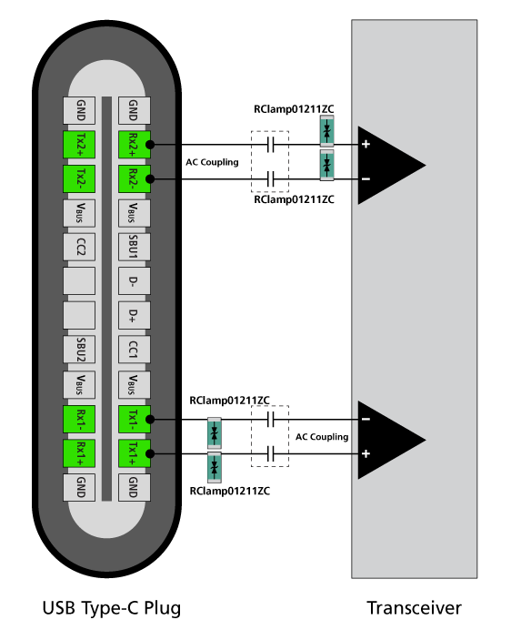 Figure 4. Protection of Tx, Rx lines of USB4 applications
Additionally, in USB4 applications, an AC-coupling capacitor is required for both the Rx and the Tx differential lines. In this way, only the AC signal is coupled between the host and the connector, and no DC current can flow through them. Also, it can store ESD currents until power is dissipated to the ground in the event of a short from VBUS. For the Rx differential lines, the TVS diode should be placed on the transceiver side of the capacitor. The TVS diode is placed between the transmitter and the AC coupling capacitor on the Tx line. Figure 4 shows the connection diagram of the RClamp01211ZC while protecting the Tx, Rx SuperSpeed USB differential lines in a USB Type-C connector with USB4 standard.
VBUS pin: Another critical consideration is power transmission. USB4 supports power delivery (USB-PD) like the previous USB specifications. If the host and the peripheral both have a USB-PD option available, USB Type-C can deliver up to 100W of power. When utilizing USB-PD, peripheral devices can select a VBUS voltage of up to 20V with a maximum current of 5A. If USB PD is not required for any application, the VBUS can support 5V at 3A, making it 15W deliverable power. Naturally, the security of the VBUS pin requires an ESD protection device with more than 20V operating voltage, fast response time, and low clamping voltage for the protection of the VBUS pin. Low capacitance is not a consideration for the VBUS line as it is generally not sensitive to additional capacitance.
The new SurgeSwitch™TDS2211P device is ideally suited to safeguard the VBUS pin of the USB Type-C connector. SurgeSwitch does not use a conventional PN junction TVS diode for protection. Instead, it uses a surge-rated FET as the primary protection element, which is used as a voltage-controlled switch. This circuit brings substantial advantages in protecting USB interfaces from ESD and EOS events. One advantage worth mentioning here is the nearly constant clamping voltage across the rated peak pulse current range (Figure 5). The clamping also remains stable over the operating temperature range. Another significant advantage is that the clamping voltage of TDS2211P is at least 30% less than the conventional TVS ESD protection devices (Figure 6). TDS2211P has an operating voltage of 22V to protect the USB-PD controllers during ESD and surge events. It offers a minimum breakdown voltage of 25V and a peak pulse current of 40A (tp=8/20us). TDS2211P provides transient protection as per the specification in IEC 61000-4-2 (ESD) at ±30kV (Air), ±30kV (Contact). This part is available in a DFN package with a 1.6 x 1.6 x 0.55 mm nominal dimension.

Figure 5. Ipp vs. VClamp in TDS2211P
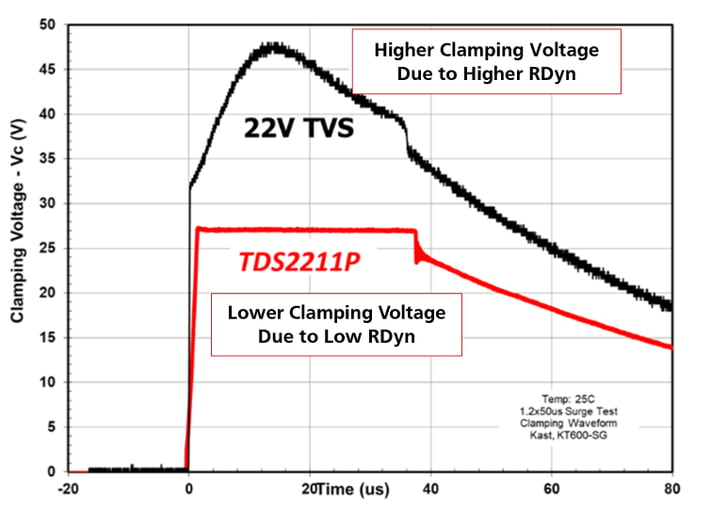 Figure 6. Lower clamping voltage of TDS2211P
D+/D- Differential Lines: D+/D- lines are used for USB 2.0 interfaces. D+ and D- pins carry a differential 480Mbps data signal, and the voltages on these differential lines can reach 5V under normal operating conditions. D+/D- lines can be protected by using Semtech's RClamp4041ZA (Figure 7). RClamp4041ZA is a 4V TVS diode. It provides a low typical junction capacitance of 0.53pF, low dynamic resistance of 0.07Ω and up to 20A peak pulse current (tp=8x20us) capability in a tiny 0201 (0.6 x 0.3 x 0.25mm) package.
CC, SBU and VCONN pins: The configuration channel (CC) pins of USB Type-C play a significant role in the USB4 protocol. The CC pin allows the USB Type-C to work as a dual-role power port to establish and manage the source and sink connection between the two attached ports.
There are two CC pins in the receptacle and one CC pin in the plug to detect the plug orientation and establish USB4 data bus communication. The other unused CC pin is utilized as a VCONN pin for a USB Type-C electronically marked cable (EMC). EEMCs require a VCONN pin to supply power (5V, 1W) to the marker electronics inside the cable. If the cable is not electronically marked, there are no electronics inside the cable and no need for a VCONN pin to supply power. In that case, the VCONN pin remains floating on the USB Type-C plug.
There are two Side Band Use (SBU) pins in USB Type-C. SBU is the auxiliary channel for DisplayPort and other data signals to work in Alt mode. In USB4 protocol, they are called SBTX and SBRX. SBTX is a serial transmit signal from USB4 Controller, and SBRX is a serial receive signal to USB4 Controller. SBTX/SBRX is used in USB4 to communicate, initialize the data line, exchange device management information, and control data between the host device and the peripheral. UART signaling with a speed of 1Mbps is used over SBTX/SBRX.
Referring to the pin configurations in Figure 2, we can see that CC/VCONN and SBU pin are next to the VBUS pin. With the USB-PD option, the VBUS pin can reach up to 20V. So, if a short circuit condition occurs, the CC/VCONN pin and SBU pins will be exposed to 20V, which can be harmful to the system. Semtech's bidirectional TVS diode µClamp®2011ZA is a perfect solution for protecting CC/VCONN and SBU pins (Figure 7). µClamp2011ZA is capable of withstanding high ESD with voltages ranging from ±30kV (Air) and ±22kV (Contact) as per IEC 61000-4-2 standard, maintaining an operating voltage of 20V. The low dynamic resistance of 0.46Ω and a minimum reverse breakdown voltage of 22V ensure system-level protection against transient events. The typical junction capacitance is only 10pF. µClamp2011ZA comes in an industry-standard ultra-small 0201 (0.6 x 0.3 x 0.25mm) packaging.
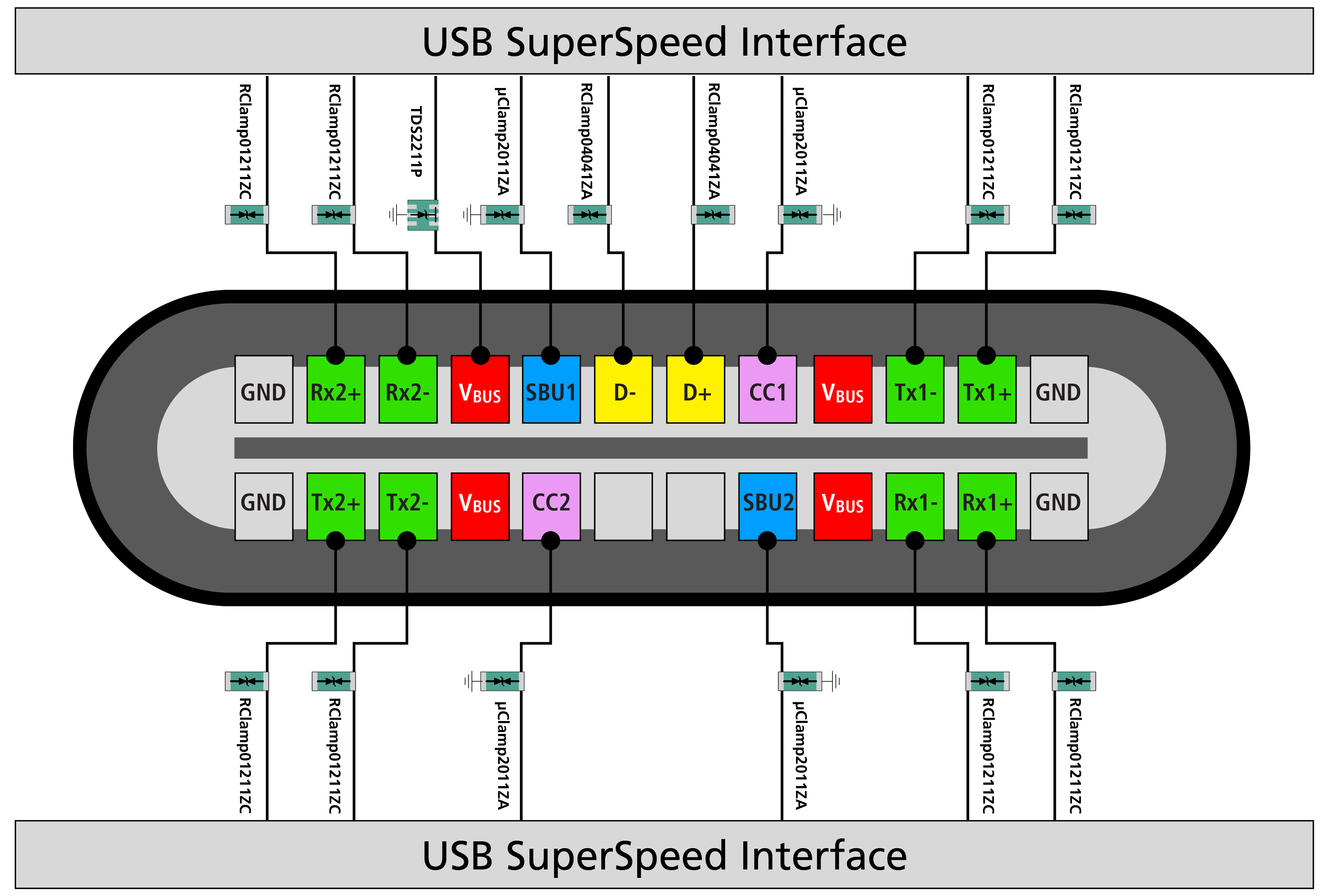 Figure 7. ESD Protection of USB4 via Type-C port
Simplifying Implementations
Semtech, via its Shield branded Protection solutions, offers a curated kit of optimized solutions for a wide range of interfaces and subsystems. The USB Shield kit is an effective design tool to expedite design implementations of USB interface.
Conclusion
The USB4 specification implemented via the USB Type-C connector has become a dominant interface that can transfer data at an ultra-fast speed of 40Gbps, support DisplayPort 2.0 and transmit power up to 100W using USB-PD mode in both directions. While the upgraded USB standards have improved the data transmission speeds and excellent video quality with greater resolution, USB Type-C ports are exposed to the frequent ESD strikes that can reach up to tens of thousands of volts – easily capable of damaging the sensitive CMOS structures of the USB4 transceiver.
As such, the USB Type-C ports must be adequately protected from all ESD threats. USB4 specification introduces some unique ESD and EOS challenges as well. Semtech's highly efficient and trusted circuit protection products, as shown in Figure 7, protect many of the world's most popular electronic devices with USB4 interfaces. No user wants to experience a piece of damaged electronic equipment due to any transient event. Semtech's solutions are ideal for safeguarding USB Type-C connectors with USB4 specification– enabling consumers to enjoy a smooth, uninterrupted experience interfacing with their high-performance electronics.
Learn more about Semtech's Circuit Protection products at the link below.

Semtech, the Semtech logo, RClamp, and µClamp are registered trademarks or service marks, and SurgeSwitch and SClamp are trademarks or service marks, of Semtech Corporation or its affiliates. USB Type-C® and USB4® are registered trademarks of the Universal Serial Bus Implementers Forum (USB-IF).