Ethernet ports are exposed to external transient events in the form of electrostatic discharge (ESD), electrical fast transient (EFT), lightning, and cable discharge events (CDE). External transient voltage suppressor (TVS) diodes are commonly used to protect the Ethernet PHY chips from these threats. However, we find that a lot of confusion exists on how to best connect the TVS diode for maximum effectiveness. Common wisdom would suggest connecting the diode near the RJ-45 connector, from each signal line to ground. In actuality, the TVS should be connected across the signal pair and located on the PHY side of the connector. In this blog, we will examine why.

Ethernet Interfaces
A typical Ethernet port includes isolation transformers, common mode chokes and port termination as shown in Figure 1. The transformers have a minimum isolation rating of 1500 VRMS (2.1kV) as required by the IEEE 802.3 standard for Ethernet interfaces. Common mode chokes are often integrated with the isolation transformers and serve to reduce EMI emissions. Ethernet ports are commonly terminated using the “Bob Smith” technique. This termination uses a 75 Ohm resistor for a common mode impedance match at each signal pair, collectively connected via a high voltage 1000pF capacitor to chassis ground. The purpose of this termination is a further reduction in common mode emissions.
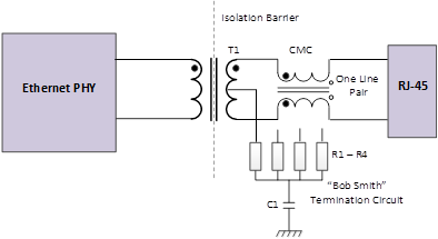
Figure 1 – Ethernet Interface Components © Semtech Corporation 2020
Common Mode & Differential Mode Surges
Transient events, which affect Ethernet ports, can be either common mode or differential mode in nature. During a common mode surge, all conductors develop the same instantaneous voltage with respect to ground. Since all conductors are at the same potential, current does not flow from one conductor to another, but instead flows through the equipment to the ground. A common path for current to flow is through the conductor to the ground via the transformer center tap and the Bob Smith termination circuit (Figure 2).
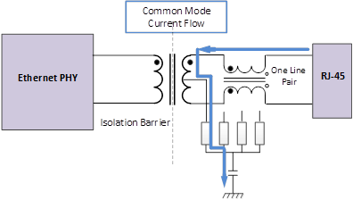
Figure 2 – Common Mode Surge Current © Semtech Corporation 2020
A surge which appears between two conductors in the same cable is called a “differential surge.” In this case, current will flow into the Ethernet port on one line of a differential pair, through the transformer and out of the port on the other line. The transient current that flows through the transformer primary charges the windings and induces surge current on the secondary (Figure 3).
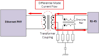
Figure 3 – Differential Mode Surge Current © Semtech Corporation 2020
Equipment test standards usually specify if the test surge is to be applied in common mode and/or differential mode. Lightning surge standards such as IEC 61000-4-5 require both differential and common mode surge tests. Application of ESD pulses is normally between the conductor and ground per IEC 61000-4-2. There is currently no test standard for CDE due to the variability of parameters that influence the discharge. Many manufacturers have developed their own test methods which commonly consist of charging a cable in common mode and plugging it into the RJ-45 connector. When an Ethernet cable is plugged into the connector, many possible contact sequences are possible. It is likely that one pin will contact first with subsequent pins to follow. The resulting discharge is usually in differential mode despite being charged in common mode.
Common Mode to Differential Mode Conversion
In some cases, common mode transients can be converted to differential mode transients. For example, it used to be common for engineers to connect a high voltage protection component, such as a gas discharge tube (GDT), on the line side of the port between each conductor and ground for suppression of lightning induced transients. For a common mode surge, the theory is that the GDTs will simultaneously trigger and conduct the current to ground. In reality, GDTs never trigger at the same voltage. One GDT will fire first, effectively grounding that line and resulting in fast rise time differential transients on the other lines.
Applying Protection Methodology
Now that we have a better understanding of the types of surges we can expect on an Ethernet port, we can clear up the confusion on how to connect the external TVS. It is clear from the discussion above that connecting a protection device on the line side of the transformer causes more problems than it solves. Moreover, in practice it is not needed. The transformer isolation and the termination network provide protection against common mode surges. As we noted, transformers in Ethernet applications have a minimum isolation voltage of 2.1kV. In reality, many commercially available transformers will actually standoff transient voltages in the 4-8kV range before the isolation is breached. The resistors and capacitor of the termination network must be chosen such that the voltage and current ratings are high enough to withstand ESD and EOS events. We have seen many instances in our lab where the termination capacitor was damaged during a surge test, or resistors were destroyed because they were too small to dissipate the energy from an ESD pulse.
Protection against differential surges requires the use of TVS diodes. If no external protection is present, the transceiver input protection is left to absorb the transient energy, which is transferred to the secondary by the transformer. Considering most transceivers are capable of modest ESD protection levels, the input will likely be damaged. A typical protection scheme, utilizing Semtech’s RClamp®3361P, is shown in Figure 4. Each device is connected differentially across one line pair. RClamp3361P features a low trigger voltage and a deep snap-back characteristic. This is important since the TVS is in parallel with the PHY on-chip protection. The external TVS has to clamp below the failure threshold voltage of the on-chip protection as well as limit the amount of current flowing into the PHY pins.
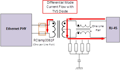
Figure 4 – Protection Circuit with RClamp3361P © Semtech Corporation 2020
Placing the protection on the PHY side of the magnetics is advantageous in that the magnitude and duration of the surge current is attenuated by the transformer windings. This is because as the surge current in the primary winding increases, the transformer saturates and stops coupling current from the primary winding to the secondary winding. The amount of attenuation will vary by vendor and configuration of the magnetics. A typical Ethernet transformer can withstand a few hundred amperes (tp=8/20us) before failure occurs, but this needs to be verified by testing.
Robust Ethernet protection can be achieved by relying on the isolation properties of the transformer along with a TVS diode located on the PHY side of the magnetics and connected across each signal line pair. Semtech offers a variety of TVS diodes for protecting 1GbE, 2.5GbE, 5GbE, and 10GbE ports. Proper selection will depend on the immunity requirements and the sensitivity of the Ethernet transceiver. The example here has been successfully used to protect against ESD per IEC 61000-4-2, CDE and lightning surges up to 500V (tp = 1.2/50μs, Rs = 42Ω).

Semtech®, the Semtech logo and RClamp® are registered trademarks or service marks of Semtech Corporation or its affiliates. Other product or service names mentioned herein may be the trademarks of their respective owners.