---
title: Advancing VBUS Protection for 48V USB Power Delivery with SurgeSwitch® Technology
description: Semtech's TDS5311P SurgeSwitch delivers near-constant 63V clamping for 48V USB PD 3.1 EPR systems — reducing downstream voltage ratings and BOM cost.
image: https://blog.semtech.com/hubfs/AMW-TDS5311%20Advancing%20VBUS%20Protection-Banner1400x600.jpg
---
[Skip to main content](https://blog.semtech.com/advancing-vbus-protection-for-48v-usb-power-delivery-with-surgeswitch-technology-1#content)
- [Cross Reference](https://www.semtech.com/design-support/cross-reference-search)
- [Parametric](https://www.semtech.com/design-support/parametric-search)
- [Shop](https://www.semtech.com/shop)
- [Investors](https://investors.semtech.com/)
- [mySemtech](https://semtech.my.site.com/DP/)
- EN
- [EN](https://www.semtech.com/)
- [CN (中文)](https://www.semtech.cn/)
- [JP (日本語)](https://www.semtech.jp/)
- [FR](https://www.semtech.fr/)
[](https://www.semtech.com)
- [LoRa®](https://www.semtech.com/lora)
- [LoRa® Overview](https://www.semtech.com/lora)
### LoRa Overview
LoRa is the de facto wireless platform of Internet of Things (IoT). Semtech's LoRa chipsets connect sensors to the Cloud and enable real-time communication of data and analytics that can be utilized to enhance efficiency and productivity.
[Read More](https://www.semtech.com/lora)
- [LoRa (PHY)](https://www.semtech.com/lora/what-is-lora)
- [Benefits of LoRa](https://www.semtech.com/lora/why-lora)
- [LoRaWAN® Standard](https://www.semtech.com/lora/lorawan-standard)
- [Products](https://www.semtech.com/products/wireless-rf)
- [Applications](https://www.semtech.com/lora/lora-applications)
### Applications Overview
With an ever-increasing number of IoT vertical applications, LoRa devices and the LoRaWAN standard is creating business efficiencies and improving lives around the world.
[Read More](https://www.semtech.com/lora/lora-applications)
- [Agriculture](https://www.semtech.com/lora/lora-applications/smart-agriculture)
- [Cities](https://www.semtech.com/lora/lora-applications/smart-cities)
- [Environment](https://www.semtech.com/lora/lora-applications/smart-environment)
- [Healthcare](https://www.semtech.com/lora/lora-applications/smart-healthcare)
- [Buildings](https://www.semtech.com/lora/lora-applications/smart-buildings)
- [Homes](https://www.semtech.com/lora/lora-applications/smart-homes)
- [Industrial Control](https://www.semtech.com/lora/lora-applications/smart-industrial-control)
- [Retail](https://www.semtech.com/lora/lora-applications/smart-retail)
- [Supply Chain and Logistics](https://www.semtech.com/lora/lora-applications/smart-supply-chain-logistics)
- [Electricity](https://www.semtech.com/lora/lora-applications/smart-electricity-metering)
- [Gas](https://www.semtech.com/lora/lora-applications/smart-gas-metering)
- [Water](https://www.semtech.com/lora/lora-applications/smart-water-metering)
- [Ecosystem](https://www.semtech.com/lora/ecosystem)
### Ecosystem Overview
LoRa is bolstered by a diverse global ecosystem of hardware manufacturers, software designers, network providers, and industry associations.
[Read More](https://www.semtech.com/lora/ecosystem)
- [LoRa Alliance®](https://www.semtech.com/lora/ecosystem/lora-alliance)
- [Featured Sensor Use Cases](https://www.semtech.com/lora/ecosystem/sensor-features)
- [Gateways](https://www.semtech.com/lora/ecosystem/gateways)
- [Software](https://www.semtech.com/lora/ecosystem/software)
- [Networks](https://www.semtech.com/lora/ecosystem/networks)
- [Industry Alliances](https://www.semtech.com/lora/ecosystem/industry-alliances)
- [Resources](https://www.semtech.com/lora/resources)
### Resources Overview
Explore our top resources to help you learn more about LoRa devices and the LoRaWAN standard or bring a LoRa-based solution to market.
[Read More](https://www.semtech.com/lora/resources)
- [LoRa Products Overview](https://www.semtech.com/lora/resources)
- [Videos](https://www.semtech.com/lora/resources/lora-videos)
- [White Papers & Use Cases](https://www.semtech.com/lora/resources/lora-white-papers)
- [LoRa Developers & Tech Support](https://www.semtech.com/lora/resources/lora-community)
- [LoRa Calculator](https://www.semtech.com/design-support/lora-calculator)
- [Amazon Sidewalk](https://info.semtech.com/sidewalk)
- [Academy for LoRaWAN](https://www.semtech.com/lora/resources/lorawan-academy)
- [Logo Use](https://www.semtech.com/company/brand-resources)
- [Press Releases](https://www.semtech.com/company/press/category/pr-lora-wireless-rf)
- [Press Coverage](https://www.semtech.com/company/news/category/pr-lora-wireless-rf)
- [Contact](https://www.semtech.com/company/contact/support)
- [Products](https://www.semtech.com/products)
- [Products Overview](https://www.semtech.com/products)
### Products Overview
Thousands of customers worldwide rely on our diverse product portfolio and world class technology roadmap for solutions in low power wireless communications, optical data transport, video broadcasting, power management, circuit protection, touch sensing, and more.
[Read More](https://www.semtech.com/products)
### Quick Links
- [Product Selector Guides](https://www.semtech.com/design-support/product-guides)
- [Shop](https://www.semtech.com/shop)
- [Parametric Search](https://www.semtech.com/design-support/parametric-search)
- [LoRa® Wireless RF](https://www.semtech.com/products/wireless-rf)
### Products Overview
LoRa®, a long range, low power platform, and the de facto wireless platform of Internet of Things, is highly integrated and cost-effective, boasting a notable battery life of up to 20 years, a 3-mile range in urban environments and a 30-mile range outdoors.
[Read More](https://www.semtech.com/products/wireless-rf)
- [ICs for Gateways](https://www.semtech.com/products/wireless-rf/lora-core)
- [ICs for Sensors](https://www.semtech.com/products/wireless-rf/lora-connect)
- [LoRa Cloud™](https://loracloud.com)
- [Software Library](https://www.semtech.com/products/wireless-rf/software-library-protocol-solution)
- [Circuit Protection](https://www.semtech.com/products/circuit-protection)
### Products Overview
Sophisticated devices that protect sensitive circuitry from Electrostatic Discharge (ESD), Electrical Fast Transients (EFT), Cable Discharge Events (CDE), and other electrical overstress.
[Read More](https://www.semtech.com/products/circuit-protection)
### Circuit Protection Products
- [ESD Protection Diodes](https://www.semtech.com/products/circuit-protection/esd-protection)
- [TVS Diodes](https://www.semtech.com/products/circuit-protection/tvs-diodes)
### Interfaces
- [Antenna](https://www.semtech.com/products/circuit-protection/antenna)
- [Automotive Ethernet](https://www.semtech.com/products/circuit-protection/automotive-ethernet)
- [Automotive High Speed](https://www.semtech.com/products/circuit-protection/automotive-high-speed)
- [Ethernet](https://www.semtech.com/products/circuit-protection/ethernet)
- [HDMI](https://www.semtech.com/products/circuit-protection/hdmi)
- [RS-485](https://www.semtech.com/products/circuit-protection/rs485)
- [USB](https://www.semtech.com/products/circuit-protection/usb)
- [VBUS](https://www.semtech.com/products/circuit-protection/vbus)
- [Signal Integrity](https://www.semtech.com/products/signal-integrity)
### Products Overview
A comprehensive portfolio of innovative optical, analog and mixed-signal semiconductor solutions that serve the rising global demand for high-speed data transmission products.
[Read More](https://www.semtech.com/products/signal-integrity)
- [Clock & Data Recovery](https://www.semtech.com/products/signal-integrity/clock-and-data-recovery)
- [Laser Drivers and Transceivers](https://www.semtech.com/products/signal-integrity/laser-drivers-transceivers)
- [Limiting Amplifiers](https://www.semtech.com/products/signal-integrity/limiting-amplifiers)
- [ROSAs](https://www.semtech.com/products/signal-integrity/rosas)
- [Signal Conditioners](https://www.semtech.com/products/signal-integrity/signal-conditioners)
- [Transimpedance Amplifiers](https://www.semtech.com/products/signal-integrity/transimpedance-amplifiers)
- [Professional AV](https://www.semtech.com/products/professional-av)
### Products Overview
Advanced off-the-shelf technology that enables end-to-end systems and integrates advanced inline signal processing capabilities such as light compression, broadcast quality scaling and audio down-mixing.
[Read More](https://www.semtech.com/products/professional-av)
- [BlueRiver®](https://www.semtech.com/products/professional-av/blueriver)
- [USB Extension](https://www.semtech.com/products/professional-av/usb-extension)
- [PerSe® Smart Sensing](https://www.semtech.com/products/perse-smart-sensing)
### Products Overview
Ultra-low power, feature-rich touch controllers that are optimized for numerous applications and provide best-in-class sensitivity with robust noise immunity to enhance touch and near range proximity detection.
[Read More](https://www.semtech.com/products/perse-smart-sensing)
- [PerSe® Connect](https://www.semtech.com/products/perse-smart-sensing/perse-connect)
- [PerSe® Contact](https://www.semtech.com/products/perse-smart-sensing/perse-contact-human-sensor)
- [PerSe® Control](https://www.semtech.com/products/perse-smart-sensing/perse-control-touch-proximity-sensor)
- [IO Expanders](https://www.semtech.com/products/perse-smart-sensing/io-expanders)
- [Broadcast Video](https://www.semtech.com/products/broadcast-video)
### Products Overview
Award-winning solutions designed specifically to push real-world broadcast boundaries in performance, reach, power, and signal integrity while reducing time to market and design risks.
[Read More](https://www.semtech.com/products/broadcast-video)
- [AV Interface & Protocol Conversion](https://www.semtech.com/products/broadcast-video/av-interface-protocol-conversion)
- [Configurable EQ/CD](https://www.semtech.com/products/broadcast-video/configurable-eq-cd)
- [Cable Drivers](https://www.semtech.com/products/broadcast-video/cable-drivers)
- [Cable Equalizers](https://www.semtech.com/products/broadcast-video/cable-equalizers)
- [Crosspoints](https://www.semtech.com/products/broadcast-video/crosspoints)
- [Receivers (Deserializers)](https://www.semtech.com/products/broadcast-video/receivers-deserializers)
- [Reclocking](https://www.semtech.com/products/broadcast-video/reclocking)
- [Transmitters (Serializers)](https://www.semtech.com/products/broadcast-video/transmitters-serializers)
- [Power Management](https://www.semtech.com/products/power-management)
### Products Overview
A pioneer in power management ICs across networking and industrial power, handheld power and automotive applications, Semtech leads the quest to enable a new class of greener, smarter and smaller end products.
[Read More](https://www.semtech.com/products/power-management)
- [EcoBrite LED Drivers](https://www.semtech.com/products/power-management/ecobrite-led-drivers)
- [EcoSpeed DC-DC Converters](https://www.semtech.com/products/power-management/ecospeed-dc-dc-converters)
- [FemtoBuck DC-DC Regulators and Controllers](https://www.semtech.com/products/power-management/femtobuck-dc-dc-regulators-controllers)
- [FemtoSwitch Load Switch ICs](https://www.semtech.com/products/power-management/femtoswitch-switches)
- [nanoSmart LDOs](https://www.semtech.com/products/power-management/nanosmart-ldos)
- [Neo-Iso Solid State Relays](https://www.semtech.com/products/power-management/neo-iso-solid-state-relays)
- [Special Functions](https://www.semtech.com/products/power-management/special-functions)
- [Cellular IoT Solutions](https://www.semtech.com/products/cellular-iot-solutions)
### Products Overview
Leading edge-to-Cloud solutions delivering the device, software and connectivity services needed to simplify and accelerate data-driven transformation with cellular IoT.
[Read More](https://www.semtech.com/products/cellular-iot-solutions)
- [Managed Connectivity](https://www.semtech.com/products/cellular-iot-solutions/managed-connectivity)
- [Modules](https://www.semtech.com/products/cellular-iot-solutions/modules)
- [Router Solutions](https://www.semtech.com/products/cellular-iot-solutions/router-solutions)
- [Technology](https://www.semtech.com/technology)
- [Technology Overview](https://www.semtech.com/technology)
### Technology Overview
Our highly differentiated, disruptive analog and mixed-signal semiconductors and advanced algorithms enable today's most innovative electronics within some of the fastest growing verticals and markets.
[Read More](https://www.semtech.com/technology)
### Quick Links
- [Related Applications](https://www.semtech.com/applications)
- [LoRa White Papers & Infographics](https://www.semtech.com/lora/resources/lora-white-papers)
- [Product Selector Guides](https://www.semtech.com/design-support/product-guides)
- [LoRa® Wireless RF For The IoT](https://www.semtech.com/lora)
### LoRa Wireless RF For The IoT Overview
LoRa is the de facto wireless platform of Internet of Things (IoT). Semtech's LoRa chipsets connect sensors to the Cloud and enable real-time communication of data and analytics that can be utilized to enhance efficiency and productivity.
[Read More](https://www.semtech.com/lora)
- [LoRa (PHY)](https://www.semtech.com/lora/what-is-lora)
- [Benefits of LoRa](https://www.semtech.com/lora/why-lora)
- [LoRaWAN® Standard](https://www.semtech.com/lora/lorawan-standard)
- [PerSe® Smart Sensing](https://www.semtech.com/technology/perse)
### PerSe® Smart Sensing Overview
Semtech's PerSe technology intelligently senses human presence for optimized connectivity and enhanced user experience.
[Read More](https://www.semtech.com/technology/perse)
### Quick Links
- [Infographic](https://info.semtech.com/perse-smart-sensing-infographic)
- [Brochure](https://www.semtech.com/uploads/common/PerSe_One_Pager.pdf)
- [Blogs](https://blog.semtech.com/topic/perse)
- [Products](https://www.semtech.com/products/perse-smart-sensing)
- [Tri-Edge™ PAM4 CDR](https://www.semtech.com/technology/tri-edge)
### Tri-Edge PAM4 CDR Overview
Tri-Edge is a CDR platform optimized for PAM4 optical interconnect in next-generation 200G and 400G data center module and AOC applications.
[Read More](https://www.semtech.com/technology/tri-edge)
### Quick Links
- [Tri-Edge White Paper](https://info.semtech.com/en/tri-edge-white-paper)
- [Product Selector Guide](https://www.semtech.com/uploads/design-support/Semtech_Optical_Product_Guide.pdf)
- [Open Eye MSA](https://www.openeye-msa.org/)
- [BlueRiver Platform For SDVoE™](https://www.semtech.com/technology/blueriver)
### BlueRiver Platform For SDVoE™
BlueRiver AV-over-IP chipsets are the world’s only chipsets to transport uncompressed, zero-latency Ultra HD/4K HDR over standard Ethernet and are the foundation for Software Defined Video Over Ethernet (SDVoE) technology.
[Read More](https://www.semtech.com/technology/blueriver)
- [BlueRiver OVERVIEW](https://www.semtech.com/technology/blueriver)
- [BlueRiver APPLICATIONS](https://www.semtech.com/technology/blueriver-applications)
- [BlueRiver VERTICAL MARKETS](https://www.semtech.com/technology/blueriver-vertical-markets)
- [SDVoE ALLIANCE®](https://www.semtech.com/technology/blueriver-sdvoe)
- [Circuit Protection](https://www.semtech.com/technology/esd-protection)
### Circuit Protection Overview
Semtech is leading the way in Transient Voltage Suppression (TVS) protection solutions that safeguard electronics systems against damage or latch-up caused by electrostatic discharge (ESD), lightning (surge), and other destructive voltage transients.
[Read More](https://www.semtech.com/technology/esd-protection)
- [Circuit Protection Overview](https://www.semtech.com/technology/esd-protection)
- [Z-Platform](https://www.semtech.com/technology/z-platform)
- [Design Resources](https://www.semtech.com/design-support/)
- [Design Resources Overview](https://www.semtech.com/design-support/)
### Design Resources Overview
Semtech places a high importance on delivering superior design support and provides a wealth of tools and resources with the goal of shortening your time to revenue for your new product introductions.
[Read More](https://www.semtech.com/design-support/)
- [Product Guides](https://www.semtech.com/design-support/product-guides)
- [Development Support Documentation](https://www.semtech.com/design-support/development-support-documents/)
- [Parametric Search](https://www.semtech.com/design-support/parametric-search)
- [Quality Assurance](https://www.semtech.com/quality/search-pb-lead-free-rohs-green)
- [LoRa GitHub](https://github.com/LoRa-Net)
- [LoRa PCB Design Review](https://info.semtech.com/pcb-design-review-service)
- [LoRa Calculator](https://www.semtech.com/design-support/lora-calculator)
- [LoRaWAN Academy and Training](https://learn.semtech.com/)
- [Product Cross Reference Search](https://www.semtech.com/design-support/cross-reference-search)
- [Frequently Asked Questions](https://www.semtech.com/design-support/faq)
- [mySemtech Document Portal](https://semtech.my.site.com/DP/)
- [IoT Applications](https://www.semtech.com/applications)
### Internet of Things
Award-winning LoRa Technology, ESD and surge protection, and smart control platforms for Internet of Things-enabled devices and low power, wide area network (LPWAN) infrastructure.
[Read More](https://www.semtech.com/applications)
- - [Smart Agriculture](https://www.semtech.com/applications/internet-of-things/smart-agriculture)
- [Smart Buildings](https://www.semtech.com/applications/internet-of-things/smart-building-automation)
- [Smart Cities](https://www.semtech.com/applications/internet-of-things/smart-cities)
- [Smart Emergency](https://www.semtech.com/applications/internet-of-things/smart-emergency-response)
- [Smart Environment](https://www.semtech.com/applications/internet-of-things/smart-environment)
- [Smart Healthcare](https://www.semtech.com/applications/internet-of-things/smart-healthcare)
- [Smart Home](https://www.semtech.com/applications/internet-of-things/smart-home-automation)
- [Smart Industrial](https://www.semtech.com/applications/internet-of-things/smart-industrial-iot)
- [Smart Logistics](https://www.semtech.com/applications/internet-of-things/logistics-supply-chain-management)
- [Smart Utilities](https://www.semtech.com/applications/internet-of-things/smart-utilities)
- [Smart Consumer](https://www.semtech.com/applications/internet-of-things/smart-consumer)
- [Professional AV Applications](https://www.semtech.com/applications/pro-av-applications)
### Professional AV
AptoVision BlueRiver™ Technology uses commercial-off-the-shelf Ethernet networks to deliver higher performance, flexibility, and scalability to the Pro AV industry.
[Read More](https://www.semtech.com/applications/pro-av-applications)
- - [AV Over IP](https://www.semtech.com/applications/pro-av-applications/av-over-ip)
- [BYOM Video Conferencing](https://www.semtech.com/applications/pro-av-applications/byom-video-conferencing)
- [HDMI Extender](https://www.semtech.com/applications/pro-av-applications/hdmi-extension)
- [HDMI Wall Plates](https://www.semtech.com/applications/pro-av-applications/hdmi-wallplates)
- [Hybrid AV Distribution](https://www.semtech.com/applications/pro-av-applications/hybrid-av-distribution)
- [KVM Switches](https://www.semtech.com/applications/pro-av-applications/kvm-switches)
- [Multiviewers](https://www.semtech.com/applications/pro-av-applications/multiviewers)
- [Point-to-Point Matrix Switching](https://www.semtech.com/applications/pro-av-applications/point-to-point-matrix-switching)
- [Presentation Switchers](https://www.semtech.com/applications/pro-av-applications/presentation-switchers)
- [SDI Equipment](https://www.semtech.com/applications/pro-av-applications/sdi-equipment)
- [SDVoE™ Integration](https://www.semtech.com/applications/pro-av-applications/sdvoe-integration)
- [Smart Display Modules (SDM)](https://www.semtech.com/applications/pro-av-applications/smart-display-modules-sdm)
- [USB-C](https://www.semtech.com/applications/pro-av-applications/usb-c)
- [Video Walls](https://www.semtech.com/applications/pro-av-applications/video-walls)
- [Other Applications](https://www.semtech.com/applications)
### Other Applications
Award-winning LoRa Technology, ESD and surge protection, and smart control platforms for Internet of Things-enabled devices and low power, wide area network (LPWAN) infrastructure.
[Read More](https://www.semtech.com/applications)
- [Automotive](https://www.semtech.com/applications/automotive-apps)
- [Advanced Driver Assistance Systems](https://www.semtech.com/applications/automotive-apps/adas-body-electronics)
- [Automotive Battery Management Systems](https://www.semtech.com/applications/automotive-apps/automotive-battery-management-systems)
- [Automotive USB Charger](https://www.semtech.com/applications/automotive-apps/dashboard-electronics-usb-charging)
- [Infotainment Unit](https://www.semtech.com/applications/automotive-apps/navigation-infotainment)
- [Remote Keyless Entry](https://www.semtech.com/applications/automotive-apps/remote-keyless-entry)
- [Telematics Unit](https://www.semtech.com/applications/automotive-apps/telematics-unit)
- [Broadcast Video](https://www.semtech.com/applications/broadcast-video-applications)
- [Broadcast Equipment](https://www.semtech.com/applications/broadcast-video-applications/broadcast-equipment)
- [Consumer Electronics](https://www.semtech.com/applications/consumer-electronics)
- [Mobile Devices](https://www.semtech.com/applications/consumer-electronics/mobile-devices)
- [Wearables](https://www.semtech.com/applications/consumer-electronics/wearables)
- [TVs, Set Top Boxes, Monitors](https://www.semtech.com/applications/consumer-electronics/tvs-set-top-boxes-monitors)
- [Laptops, Tablets, Computers](https://www.semtech.com/applications/consumer-electronics/laptops-tablets-computers)
- [Appliances & White Goods](https://www.semtech.com/applications/consumer-electronics/appliances-white-goods)
- [Computers, Printers, Scanners](https://www.semtech.com/applications/consumer-electronics/computers-printers-scanners)
- [Industrial](https://www.semtech.com/applications/industrial-applications)
- [Medical Equipment](https://www.semtech.com/applications/industrial-applications/medical-equipment)
- [Factory Automation](https://www.semtech.com/applications/industrial-applications/factory-automation)
- [Energy, Smart Grids, Smart Metering](https://www.semtech.com/applications/industrial-applications/energy-smart-grids-smart-metering)
- [Surveillance](https://www.semtech.com/applications/industrial-applications/surveillance)
- [Test & Measurement](https://www.semtech.com/applications/industrial-applications/test-measurement)
- [Power Tools](https://www.semtech.com/applications/industrial-applications/power-tools)
- [Infrastructure](https://www.semtech.com/applications/infrastructure)
- [Data Centers](https://www.semtech.com/applications/infrastructure/enterprise-datacenters)
- [Passive Optical Networks / Fiber to the Home](https://www.semtech.com/applications/infrastructure/enterprise-passive-optical-networks-fiber-to-the-home)
- [Broadband](https://www.semtech.com/applications/infrastructure/enterprise-broadband)
- [Networking & Optical Communications](https://www.semtech.com/applications/networking-communication)
- [Broadband](https://www.semtech.com/applications/networking-communication/broadband)
- [Passive Optical Networks / Fiber to the Home](https://www.semtech.com/applications/networking-communication/passive-optical-networks)
- [ISM Networks](https://www.semtech.com/applications/networking-communication/ism-networks)
- [Wireless Infrastructure, Base Stations](https://www.semtech.com/applications/networking-communication/wireless-infrastructure-base-stations)
- [Data Centers](https://www.semtech.com/applications/networking-communication/datacenters)
- [Quality](https://www.semtech.com/quality)
- ### Quality Overview
Ethical standards drive peak customer satisfaction.
[Read More](https://www.semtech.com/quality)
- [Quality Overview](https://www.semtech.com/quality)
- [Reliability](https://www.semtech.com/quality/reliability)
- [Product Testing](https://www.semtech.com/quality/testing)
- [Material & Packaging Declarations](https://www.semtech.com/quality/declarations)
- [Quality & Failure Analysis](https://www.semtech.com/quality/analysis)
- [Search Pb(Lead)-Free/RoHS-Green](https://www.semtech.com/quality/search-pb-lead-free-rohs-green)
- [Environmental Initiatives](https://www.semtech.com/quality/environment)
- [Quality Policy](https://www.semtech.com/quality/policy)
- [Quality Certifications](https://www.semtech.com/quality/certifications)
- [IR Reflow Profiles](https://www.semtech.com/quality/reflow-profiles)
- [About](https://www.semtech.com/company)
- ### Company Overview
Since our founding in 1960 as a manufacturer of high reliability products, Semtech has grown to become a multinational technology innovator, enabling solutions that help to make the world a better place.
[Read More](https://www.semtech.com/company)
- [Company Overview](https://www.semtech.com/company)
- [Leadership](https://www.semtech.com/company/executive-leadership)
- [Corporate Citizenship (ESG)](https://www.semtech.com/company/corporate-citizenship)
- [Core Values](https://www.semtech.com/company/core-values)
- [News & Media](https://www.semtech.com/company/news-and-media)
- [Videos](https://www.semtech.com/company/videos)
- [Blog](https://blog.semtech.com)
- [Events](https://www.semtech.com/company/events)
- [Careers](https://www.semtech.com/careers)
- [Locations](https://www.semtech.com/company/locations/north-america)
- [Security](https://www.semtech.com/company/security)
- [Contact](https://www.semtech.com/company/contact)
- [Contact Us](https://www.semtech.com/company/contact/support)
1. [Home](https://www.semtech.com/)
2. [Blog](https://blog.semtech.com/)
15 July, 2026 4 min read
# Advancing VBUS Protection for 48V USB Power Delivery with SurgeSwitch® Technology
Anindita Bhattacharya
The USB Type-C connector has become the universal interface of modern electronics. From laptops and smartphones to Artificial Intelligence (AI) computing platforms and industrial edge devices, USB Type-C supports both high-speed data transfer and high-wattage power delivery through a single cable. With the adoption of USB Power Delivery (USB PD) 3.1 and its Extended Power Range (EPR), (Table 1) VBUS line voltages have scaled from the familiar 20V/100W standard power range to 28V, 36V and 48V — enabling power delivery of up to 240W over a USB-C cable.
This evolution brings significant design challenges. Higher VBUS voltages introduce higher clamping voltage requirements for transient protection, and conventional transient voltage suppression (TVS) diode solutions designed for this voltage level have high clamping voltages that force designers to specify downstream components with elevated voltage ratings. [Semtech's SurgeSwitch®](https://www.semtech.com/products/circuit-protection/surgeswitch/surgeswitch) technology addresses this gap, and the new [TDS5311P](https://www.semtech.com/products/circuit-protection/tvs-diodes/tds5311p) is purpose-built for 48V VBUS protection in USB PD 3.1 EPR systems.
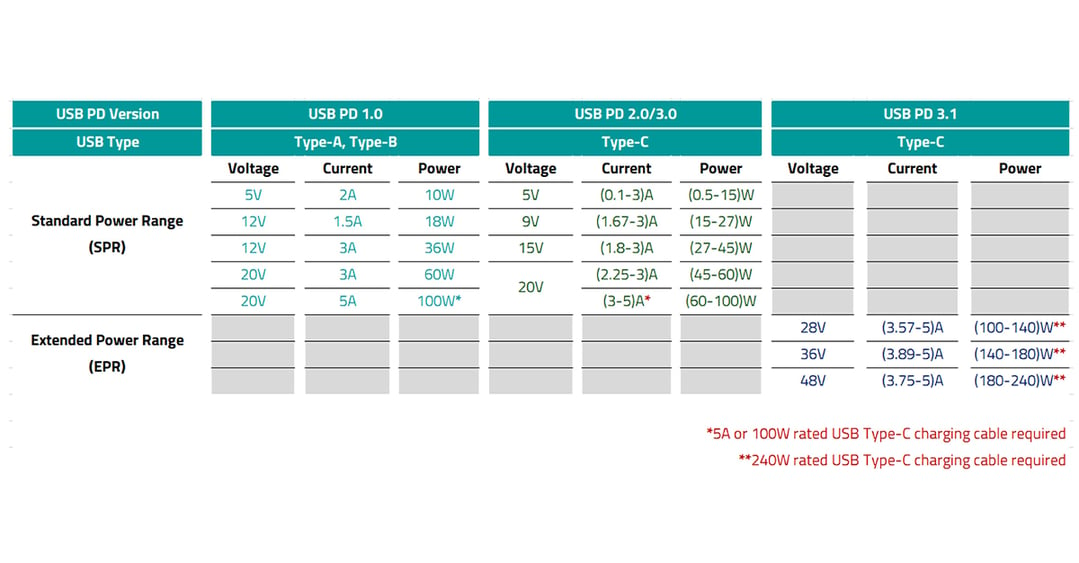
*Table 1: USB-PD Specifications*
## The Growing Threat on the VBUS Line
The VBUS pin in the USB Type-C connector carries the supply voltage to downstream devices being powered. This pin is also exposed to electrical overstress events, including electrostatic discharge (ESD), electrical fast transients (EFT), cable discharge events (CDE), and surge transients caused by lightning or power distribution switching.
These threats are not hypothetical. A single unprotected ESD event at the VBUS pin — caused by a charged user handling the connector — can damage or destroy downstream power management integrated circuits (ICs) and charging circuits. Surge events, which carry far greater energy, can produce destructive overvoltages across the entire input stage. No user wants to experience a damaged high-end computer due to an ESD or surge event. As USB PD EPR devices increasingly find their way into industrial and high-performance computing environments, the likelihood and severity of these threats grow accordingly.
*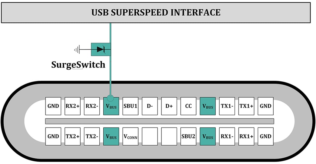*
*Figure 1: Protecting the VBUS pin with a SurgeSwitch*
## Why Clamping Voltage Is the Critical Parameter
When a transient event occurs, a TVS protection device conducts and clamps the voltage at the VBUS pin to a defined level — the clamping voltage. This is the maximum voltage the system is exposed to during a surge event, and it is the most important specification for evaluating a protection device's effectiveness.
In conventional PN junction-based TVS diodes, clamping voltage increases with surge current and rises further with temperature, which means the device's worst-case behavior occurs precisely during the most demanding conditions. Additionally, downstream components must be specified to withstand those elevated clamping voltages which drive component cost and increase the required board area.
Semtech's SurgeSwitch architecture takes a fundamentally different approach. SurgeSwitch devices are built on a MOSFET-based topology that delivers a nearly constant clamping voltage throughout the full surge current range and remains stable over the operating temperature range. The result is a clamping voltage that is up to 30% lower than equivalent conventional PN junction-based TVS diodes, providing a larger safety margin for downstream ICs and enabling engineers to select components with lower absolute maximum voltage ratings.
*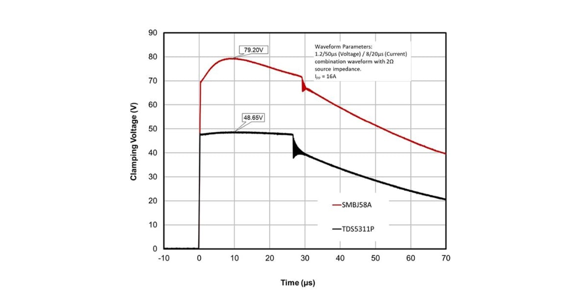*
*Figure 2: Clamping voltage vs. Time comparison chart (TDS5311P vs. conventional TVS diode (SMBM58A)*
## Introducing the TDS5311P: SurgeSwitch for 48V VBUS Protection
The TDS5311P is Semtech's latest SurgeSwitch device, engineered to address the protection requirements of 48V VBUS lines in USB PD 3.1 EPR systems. Its working voltage of 53V provides the necessary headroom above the 48V bus rail, while its MOSFET-based architecture delivers the near-constant clamping performance that high-voltage USB designs demand.
### Key Specifications
| **Parameter** | **Value** |
| --- | --- |
| Working Voltage | 53V |
| Reverse Breakdown Voltage (min.) | 57V |
| Peak Pulse Current (8/20µs) | 24A |
| Clamping Voltage (at Ipp) | 63V |
| Dynamic Resistance | 31mΩ |
| ESC (IEC 61000-4-2) | +/-20kV/+/-25kV (Contact/Air) |
| EFT (IEC 61000-4-4) | +/-4kV (100kHz and 5kHz, 5/50ns) |
| Surge (IEC 61000-4-5) | 24A (tp = 8/20μs), 1kV (tp = 1.2/50μs, RS = 42Ω) |
To illustrate the clamping voltage advantage in practical terms: a commonly used conventional TVS solution for 48V USB PD applications carries a clamping voltage of approximately 87V under similar test conditions. The TDS5311P's clamping voltage of 63V represents approximately a 24V reduction. This allows downstream components to be specified at a lower voltage tolerance, reducing both BOM cost and board space while increasing the overall design margin.
*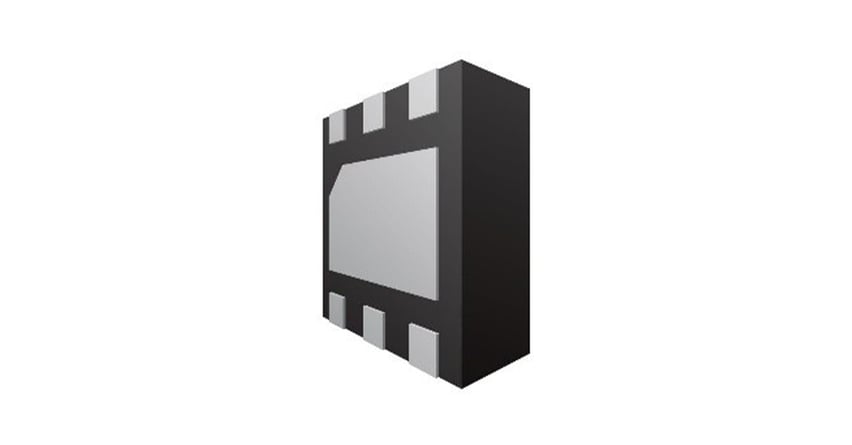*
*Figure 3: Semtech TDS5311P package diagram*
## Application: USB PD 3.1 EPR Systems
The TDS5311P is designed for applications where USB PD 3.1 EPR's 48V operating mode is in use. As shown in Figure 4, the TDS5311P is placed in parallel with the VBUS rail at the USB Type-C port entry point, providing a low-impedance clamp path to ground during transient events while remaining effectively invisible to the system under normal operating conditions.
Typical design targets for 48V USB PD EPR VBUS protection include:
- **AI laptops and computing** **devices** requiring 48V USB-C power delivery for high-wattage system loads
- **High-performance docking stations** where the VBUS rail powers multiple downstream devices simultaneously
- **Portable power stations and power banks** supporting USB PD EPR output
- **Industrial embedded computing platforms** with USB-C power input exposed to transient-rich environment
*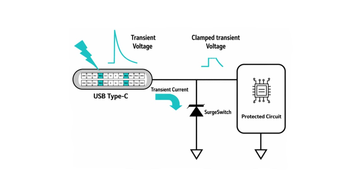*
*Figure 4: Simplified application circuit diagram showing TDS5311P placement on the VBUS line at a USB Type-C receptacle, with arrows indicating the transient current path to ground*
*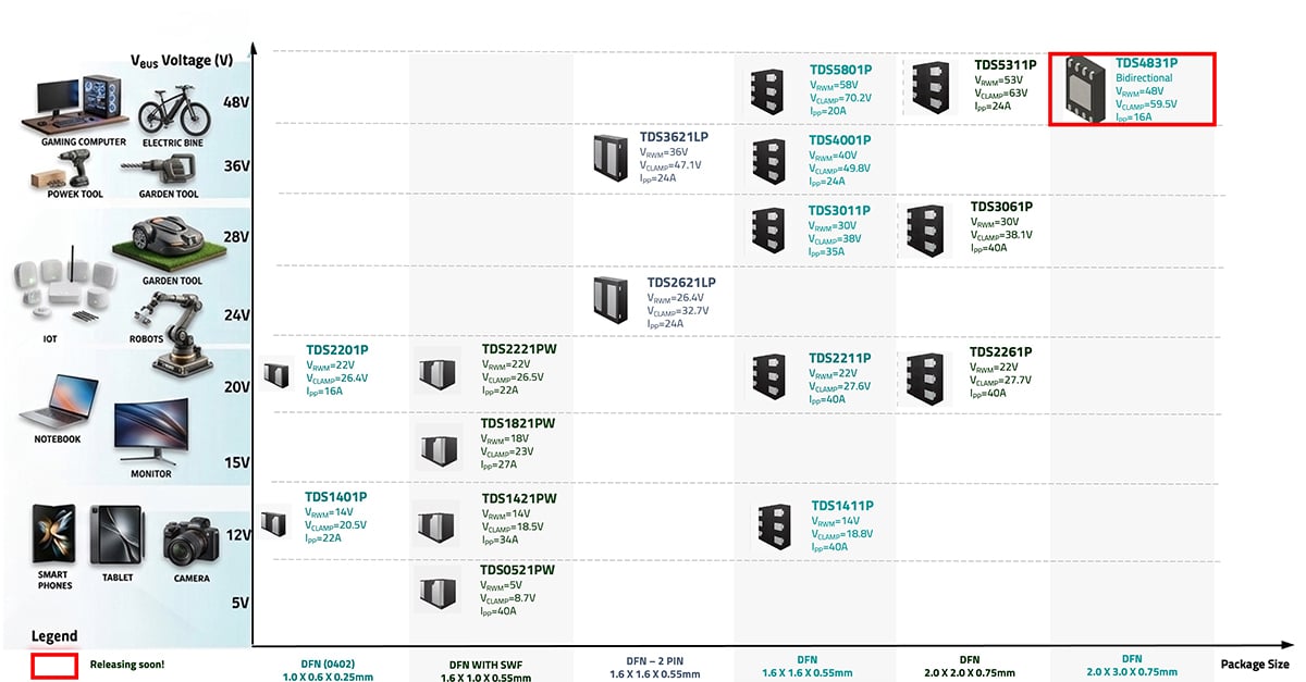*
*Figure 5: Semtech SurgeSwitch Portfolio*
## Summary
While the fundamental requirement for USB VBUS protection has not changed, the limitations of conventional solutions have become more evident. Traditional TVS diodes, though widely used, suffer from drawbacks such as higher and variable clamping voltages as well as strong temperature dependence. These characteristics make them less suitable for modern high-power applications. Semtech’s TDS5311P SurgeSwitch addresses these challenges with a nearly constant 63V clamping voltage, 24A peak pulse current capability, full IEC compliance, and the inherent advantages of a MOSFET-based architecture — providing the performance and design margin needed for reliable USB PD 3.1 EPR systems.
To learn more about the TDS5311P or to explore Semtech's complete USB Type-C circuit protection portfolio, visit [semtech.com/products/circuit-protection](http://semtech.com/products/circuit-protection).
*Semtech® and the Semtech logo are registered trademarks or service marks, and SurgeSwitch® is a registered trademark or service mark, of Semtech Corporation or its affiliates. Other product or service names mentioned herein may be the trademarks of their respective owners. *
---
[Circuit Protection](https://blog.semtech.com/topic/circuit-protection)
### Sign Up for Blog Updates
Get innovation delivered to your inbox. Sign up for our blog and stay on top of the very latest from Semtech.
### Related Blogs:
[Transient Protection of RS-485 Buses in Industrial Applications](https://blog.semtech.com/transient-protection-of-rs-485-buses-in-industrial-applications)
February 4, 2020
[Protection of IO-Link With SurgeSwitch®](https://blog.semtech.com/protection-of-io-link-with-surgeswitch)
December 21, 2021
[Complete Protection for HDMI-SDI/SDI-HDMI Converters](https://blog.semtech.com/complete-protection-for-hdmi-sdi-and-sdi-hdmi-converters)
December 8, 2022
[Semtech](https://blog.semtech.com/)
- [Sierra Wireless](https://www.sierrawireless.com/)
- [LoRa](https://www.semtech.com/lora)
- [Products](https://www.semtech.com/products)
- [Technology](https://www.semtech.com/technology)
- [Design Resources](https://www.semtech.com/design-support/product-guides)
- [About Semtech](https://www.semtech.com/company)
### Quick Links
- [Parametric Search](https://www.semtech.com/design-support/parametric-search)
- [mySemtech](https://semtech.my.site.com/DP/)
- [Blogs](https://blog.semtech.com/)
- [Careers](https://www.semtech.com/careers)
- [Contact Us](https://www.semtech.com/company/contact)
Semtech is a leading global supplier of high performance analog and mixed-signal semiconductors and advanced algorithms for infrastructure, high-end consumer and industrial equipment.
- [Facebook](https://www.facebook.com/semtechcorporation)
- [Twitter](https://twitter.com/SemtechCorp)
- [YouTube](https://www.youtube.com/user/SemtechMediacenter)
- [LinkedIn](https://www.linkedin.com/company/semtech/)
[Privacy Policy](https://www.semtech.com/legal) | [Terms & Conditions](https://www.semtech.com/terms) | [Supplier Responsibility](https://www.semtech.com/quality/policy) | [Statement Against Human Trafficking and Slavery](https://www.semtech.com/uploads/quality/semtech-statement-against-human-trafficking-and-slavery.pdf) | © 2025 All Rights Reserved
- [Home](https://www.semtech.com/)
- [LoRa](https://www.semtech.com/lora)
- [LoRa Overview](https://www.semtech.com/lora)
- [LoRa(PHY)](https://www.semtech.com/lora/what-is-lora)
- [Benefits of LoRa](https://www.semtech.com/lora/why-lora)
- [LoRaWAN® Standard](https://www.semtech.com/lora/lorawan-standard)
- [Applications](https://www.semtech.com/lora/lora-applications)
- [Ecosystem](https://www.semtech.com/lora/ecosystem)
- [Products](https://www.semtech.com/lora/lora-products)
- [Resources](https://www.semtech.com/lora/resources)
- [Products](https://www.semtech.com/products)
- [Products Overview](https://www.semtech.com/products)
- [Wireless RF](https://www.semtech.com/products/wireless-rf)
- [Circuit Protection](https://www.semtech.com/products/circuit-protection)
- [Signal Integrity](https://www.semtech.com/products/signal-integrity)
- [Professional AV](https://www.semtech.com/products/professional-av)
- [PerSe™ Smart Sensing](https://www.semtech.com/products/perse-smart-sensing)
- [Broadcast Video](https://www.semtech.com/products/broadcast-video)
- [Power Management](https://www.semtech.com/products/power-management)
- [High Reliability](https://www.semtech.com/products/high-reliability)
- [Technology](https://www.semtech.com/technology)
- [Technology Overview](https://www.semtech.com/technology)
- [LoRa Wireless RF for the IoT](https://blog.semtech.com/lora)
- [Tri-Edge™ PAM4 CDR](https://www.semtech.com/technology/tri-edge)
- [BlueRiver® PLATFORM FOR SDVoE™](https://www.semtech.com/technology/blueriver)
- [BlueRiver OVERVIEW](https://www.semtech.com/technology/blueriver)
- [BlueRiver APPLICATIONS](https://www.semtech.com/technology/blueriver-applications)
- [BlueRiver VERTICAL MARKETS](https://www.semtech.com/technology/blueriver-vertical-markets)
- [SDVoE ALLIANCE™](https://www.semtech.com/technology/blueriver-sdvoe)
- [Circuit Protection](https://www.semtech.com/technology/esd-protection)
- [Circuit Protection Overview](https://www.semtech.com/technology/esd-protection)
- [Z-Platform](https://www.semtech.com/technology/z-platform)
- [Design Resources](https://www.semtech.com/design-support)
- [Design Resources Overview](https://www.semtech.com/design-support)
- [Design Resources](https://www.semtech.com/design-support/product-guides)
- [Cross Reference Search](https://www.semtech.com/design-support/cross-reference-search)
- [Parametric Search](https://www.semtech.com/design-support/parametric-search)
- [mySemtech](https://semtech.force.com/DP)
- [Quality](https://www.semtech.com/quality)
- [Quality Overview](https://www.semtech.com/quality)
- [Reliability](https://www.semtech.com/quality/reliability)
- [Product Testing](https://www.semtech.com/quality/testing)
- [Material & Packaging Declarations](https://www.semtech.com/quality/declarations)
- [Quality & Failure Analysis](https://www.semtech.com/quality/analysis)
- [Search Pb(Lead)-Free/RoHS-Green](https://www.semtech.com/quality/search-pb-lead-free-rohs-green)
- [Environmental Initiatives](https://www.semtech.com/quality/environment)
- [Quality Policy](https://www.semtech.com/quality/policy)
- [Quality Certifications](https://www.semtech.com/quality/certifications)
- [IR Reflow Profiles](https://www.semtech.com/quality/reflow-profiles)
- [About](https://www.semtech.com/company)
- [Leadership](https://www.semtech.com/company/executive-leadership)
- [Corporate Citizenship (ESG)](https://www.semtech.com/company/corporate-citizenship)
- [Core Values](https://www.semtech.com/company/core-values)
- [News & Media](https://www.semtech.com/company/news-and-media)
- [Events](https://www.semtech.com/company/events)
- [Careers](https://www.semtech.com/careers)
- [Locations](https://www.semtech.com/company/locations/north-america)
- [Security](https://www.semtech.com/company/security)
- [Contact](https://www.semtech.com/company/contact)
- More
- [Parametric Search](https://www.semtech.com/design-support/parametric-search)
- [Shop](https://www.semtech.com/shop)
- [Investors](http://investors.semtech.com/)
- [Blog](https://www.semtech.com/blog)
- [mySemtech](https://semtech.force.com/DP)
- [Contact](https://www.semtech.com/company/contact)
```json
{
"@context" : "https://schema.org",
"@type" : "BlogPosting",
"author" : {
"@type" : "Person",
"name" : "Anindita Bhattacharya",
"url" : "https://blog.semtech.com/author/anindita-bhattacharya"
},
"dateModified" : "2026-09-10T18:32:31.036Z",
"datePublished" : "2026-07-15T17:00:00.000Z",
"headline" : "Advancing VBUS Protection for 48V USB Power Delivery with SurgeSwitch® Technology",
"image" : [ "https://blog.semtech.com/hubfs/AMW-TDS5311%20Advancing%20VBUS%20Protection-Banner1400x600.jpg" ],
"mainEntityOfPage" : {
"@id" : "https://blog.semtech.com/advancing-vbus-protection-for-48v-usb-power-delivery-with-surgeswitch-technology-1",
"@type" : "WebPage"
},
"publisher" : {
"@type" : "Organization",
"logo" : {
"@type" : "ImageObject",
"url" : "https://blog.semtech.com/hubfs/Imported%20sitepage%20images/semtech-logo.svg"
},
"name" : "Semtech"
}
}
```
```json
{
"@context": "http://schema.org",
"@type": "BlogPosting",
"mainEntityOfPage": {
"@type": "WebPage",
"@id": "https://blog.semtech.com/advancing-vbus-protection-for-48v-usb-power-delivery-with-surgeswitch-technology-1"
},
"headline": "Advancing VBUS Protection for 48V USB Power Delivery with SurgeSwitch® Technology",
"image": {
"@type": "ImageObject",
"url": "https://info.semtech.com/hubfs/AMW-TDS5311%20Advancing%20VBUS%20Protection-Banner1400x600.jpg"
},
"datePublished": "2026-07-15 17:00:00",
"dateModified": "September 10, 2026, 6:32:31 PM",
"author": {
"@type": "Person",
"name": "Anindita Bhattacharya"
},
"publisher": {
"@type": "Organization",
"name": "Semtech Corporation",
"logo": {
"@type": "ImageObject",
"url": "https://info.semtech.com/hubfs/Imported%20sitepage%20images/semtech-logo.svg"
}
},
"description": "Semtech's TDS5311P SurgeSwitch delivers near-constant 63V clamping for 48V USB PD 3.1 EPR systems — reducing downstream voltage ratings and BOM cost."
}
```